



Computed Tomography for Advanced Manufacturing. Dr Cameron Chai and Peter Ailey from AXT lead us through the tech
With Australia’s high labour cost, most high-volume manufacturing has moved offshore. As a result, there has been a shift towards low-volume, high-value manufacturing, with Australian manufacturers adopting more advanced manufacturing methodologies such as additive manufacturing. This has necessitated a similar shift to advanced non-destructive testing for quality control, with computed tomography answering the call.
Computed Tomography (CT) is a non-destructive 3D imaging technique analogous to CAT scans performed on humans. It is perfectly suited to inspecting manufactured components, especially those with complex geometries and internal structures. CT can be used to check dimensional accuracy (vs. CAD drawings), identify invisible defects beneath the surface to external inspection techniques, and investigate failures or process control and optimisation.
Origins of CT
Initially developed for medical applications in the 1970s, CT is now used more extensively in materials science, nondestructive testing (NDT), quality control, failure analysis, and geological materials investigation. In these applications, it is ideally suited to revealing subsurface defects and structures or checking manufacturing tolerances.
Although CT has been used extensively in medical applications for decades, it has taken much longer for it to become more widely accepted by the materials science and NDT communities. This is because these applications require much higher resolutions to produce meaningful data and to reveal minute defects. Higher resolution means more data, which requires better data storage and more powerful computers to process the data. In more recent times, artificial intelligence (AI) has also played a role in processing data.
Modern CT Systems
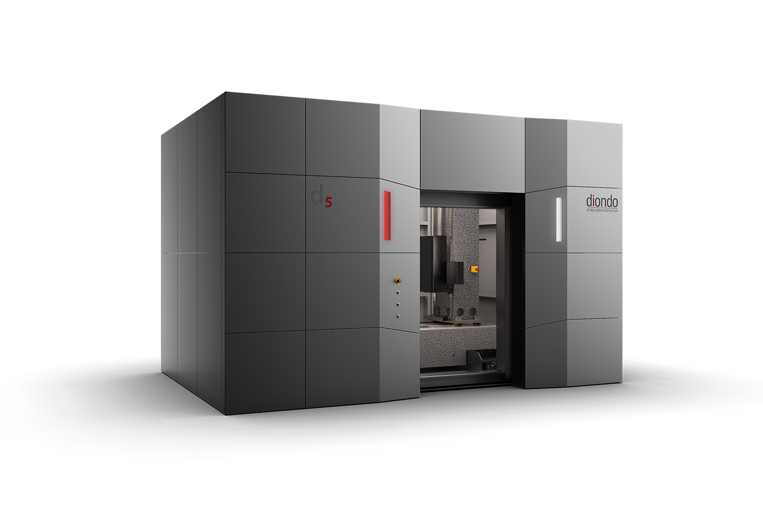
CT systems can range from small benchtop instruments and run-throughs to much larger systems catering to components and assemblies in the metre-plus range. Some systems are designed for QC applications in industrial environments and will happily live out on the factory floor where they can be integrated into your workflow. Also, depending on the smallest feature you need to detect, CT’s can offer sub-micron resolutions.
CT and radiography
In NDT, a CT system is similar to a digital radiography (DR) setup in that a sample is mounted on a stage, or manipulator, between an X-ray source and detector. X-ray photons pass through the sample, and images are collected on the detector. For DR, you generally collect one image at a time that only shows one particular slice, or projection, through the sample.
How does CT work?
CT runs on the same principle as DR. However, after each image or tomograph is acquired, the sample, or sometimes the source and detector, is rotated slightly, and another image is taken, effectively slicing up the 360 degrees (sometimes less) of rotation. Finer slices result in more projections and better resolution. As mentioned, higher resolution results in more data and longer collection times.
High-resolution scans can run into several thousand projections. Once a full rotation is completed and you have collected your data set (e.g., tiff stack), you can then use reconstruction algorithms to ‘rebuild’ the combined stack of projections, generating a 3D image of your sample. DR is a powerful tool in its own right; however, CT enables you to locate specific features within your sample precisely.
Powerful software allows the operator to analyse and manipulate the data in many ways. Packages such as Volume Graphics can easily rotate and examine the inside for cracks and defects, reconstruct and deconstruct regions of interest, take measurements, and perform other metrological operations.
These software packages also allow you to automate repetitive tasks and often incorporate Automated Defect Recognition (ADR). As the name suggests, ADR can analyse the 3D dataset, look for particular flaws, and then report back to the operator, potentially with pass/fail options. More sophisticated packages also offer finite element analysis capabilities, which can benefit product design.
Resolution and voxels
We often refer to the dimensions of 2D digital graphics in terms of pixels, with a pixel being the smallest single definable element. In 3D computer-generated renderings, the smallest element is a voxel, which can be likened to a 3D pixel or a combination of volume and pixel.
In industrial systems for more significant parts, a typical voxel size of 50µm to 200µm can be used on items like automotive gearboxes. Micro CT voxel sizes in the sub-micron range can be achieved on smaller samples in the range of pharmaceutical tablets. Still, a series of images can be stitched together, effectively providing analysis of larger objects.
These higher resolutions require high magnifications, and the X-ray source is typically very close (as close as possible) to the sample. Variables such as field of view, detector pixel size, X-ray focal spot size, magnification, etc., can influence the resolution of a CT scan.
You may also hear about temporal resolution, which refers to how quickly a CT can create a complete image slice. In industrial environments, temporal resolution may be viewed more critically as it influences throughput. Otherwise, it can be essential to monitor processes in real time, and high temporal resolutions could prevent a rapid event such as brittle failure from being missed.
Application areas for CT
As mentioned, CT is most commonly used in quality control (QC) applications, where it is ideal for manufacturers of low-volume/high-value components. In these environments, destructive testing of small percentages of parts is unfeasible, and CT can also be used to check the dimensional accuracy of manufactured parts.
Another alternative application is reverse engineering. For example, parts that are no longer in production can be converted into CAD files, which can then be used to produce 3D models.
CT has also found application in product development where it can be used to see inside components, e.g. cast components, to show pores that may result from improper mould filling. This knowledge can help manufacturers optimise processing parameters or mould designs to encourage better-molten metal flow.
Advantages of CT as an inspection tool
CT has the advantages over other NDT inspection techniques in that:
- X-rays can penetrate through complex 3D structures;
- Can easily reveal internal structures and features;
- Can see below the surface;
- Can reveal defects such as pores, voids and cracks;
- It can be used to check dimensional tolerances against specifications;
- In metal additive manufacturing, it can identify regions that may not have sintered.
Summary
CT is becoming an increasingly popular method of inspecting components nondestructively. Various systems are now available that can accommodate parts of varying sizes. CT instruments are primarily used to perform quality control checks rapidly, but they may also be used in product development or reverse engineering.
Unlike most other imaging and metrology techniques, CT can see beneath the surface of components, revealing cracks, flaws, pores and other defects. This makes it an invaluable quality control tool, particularly for high-value components manufactured in small volumes.